My Pi Description

My Experiences With the Raspberry Pi -- Tracking My Learning -- My Pi Projects

Thursday, January 7, 2016

Programming the ATmega328P Registers From the Arduino IDE

Please Note:

Because I have no experience with other Arduino boards, I'm going to confine my comments to the Arduino Uno and the Atmel ATmega328P microprocessor.

Introduction

If you desire to do something beyond the Arduino programming language, like program an interrupt for any Uno I/O pin, do more precise control of pulse width modulation, or write to the EEPROM within the ATmega328P, you need to learn about the ATmega328P's internal registers. If you are studying someone else's code and see something like:
     PORTD |= (1 << PORTD1);
and you wondered what that meant, read on. By utilizing what I call "Register Programming", besides the examples above, you can more efficiently program the three I/O ports, use the ATmega328P's internal timers, program it's SPI, I2C, and serial interfaces, and make better use of the Analog to Digital converter pins, and the analog comparator.
I would not attempt to control a servo with the AnalogWrite() function. You need more resolution than 1 part in 256. Also, the frequency is wrong. AnalogWrite() gives you a frequency of 490Hz or 980Hz depending on the pin. The very common servo I am familiar with requires a frequency of 50Hz. Register programming gives you the opportunity of using an ATmega328P counter that gives you one part 65536 resolution rather than 256. You can also set the frequency exactly to your needs.
What are these registers? They are eight bit bytes of SRAM memory within the ATmega328P. These registers can be accessed through programming via the Arduino IDE. If you write "digitalWrite(13, HIGH);" in your code, you are writing to one of these resisters. The ATmega328P has 224 of these registers, but most are reserved for future use. I count 86 that are useful. All of these have particular purposes.

Resources

To do Register Programming you need three basic resources:
  1. Comparison between Arduino I/O pins and ATmega328P pins
  2. ATmega328P datasheet
  3. AVR libraries on your computer

Arduino Pins and the ATmega328P

The following partial schematic represents the ATmega328P and the Arduino Uno's pins as printed on the device and as used in the language reference:
The graphic of ATmega328P looks really messy. That is because, all the I/O pins, except power and grounds, have multiple functions. For the moment, we will concentrate on the ATmega328P's pin nomenclature closest to the border of the graphic, namely PB0 to PB7, PC0 to PC6, and PD0 to PD7. All but three of these pins connect to Arduino Uno I/O pins. PC6 does not because it is used by the Uno as a reset to the ATmega328P. PB6 and PB7 connect to the 16MHz crystal so can not be used as I/O pins. The other pins make up three ports, B, C, and D. Each port is controlled or monitored by three ATmega328P registers.

ATmega328P Datasheet

The next resource is the Atmel datasheet for the ATmega family of microcontrollers. Here is a link to that document.
Every function and every register is clearly presented and explained in the datasheet. You can learn a lot and do a lot by reading this document. Besides the control of the port registers, I have used the timer registers to precisely control motors and servos (better than using the Arduino's analogWrite() function). I have also used the registers for writing to and reading from the ATmega328P's internal EEPROM, and I have used them to utilize external interrupts.

ATmega328P Port Registers

Let's create an example using one of the three port registers. We will use all eight pins of port D. Four LEDs will connect to PD0 to PD3. These correspond to pins labeled 0 to 3 on the Uno. We will connect four switches to PD4 to PD7. These correspond to pins labeled 4 to 7 on the Uno. Here is the partial schematic:
The following is copied directly from the datasheet for the ATmega328P. It details the three registers devoted to Port D:

AVR Libraries On Your Computer

Here is the final resource. YOU DO NOT NEED TO CONSULT THESE LIBRARIES TO PROGRAM YOUR DEVICES. I include this discussion to show why the Arduino IDE compiler allows you to use the Atmel register and register bit names in your code.
Atmel has supplied libraries for a large number of their microcontrollers to the Arduino development suite. If you have a PC, more than likely, you will find these libraries here:
     C:\Program Files (x86)\Arduino\hardware\tools\avr\avr\include\avr.
There are 285 library files in this directory. No matter what version of the Arduino you have, you only need to know of one these libraries: io.h. You insert "#include <avr\io.h>" at the top of your code. The Arduino IDE, when compiling, will look at this file and knowing the specific Arduino you are using, will go to the appropriate library file. For the Arduino Uno, that library is iom328p.h. Wish I could print out the entire file here, but it is quite long.
iom328p.h consists of many, many #define statements. There is a #define for each of the ATmega328P's registers, and #define statements for each bit of each register. I never counted them, but I would think all 86 registers are addressed. All the nomenclature in the library is taken directly from the data sheet. PORTD in the data sheet is PORTD in the library. Consequently, you can write "PORTD" in your code.
Here is the portion of the library that deals with the three PORTD registers. Note the text corresponds exactly to the text in the data sheet:

Putting It All Together and Writing Code

While the text in the library conforms to the text in the data sheet register descriptions, the text on the schematic (also taken from the data sheet) does not. For example, the schematic pin labeled PD7 corresponds to PORTD7 in the PORTD register, PIND7 in the PIND register, and DDD7 in the DDRD register.
Now that we know that we can use the register names, like DDRD, and the register individual bit names, like DDD2, how do we write code? There are two basic ways I do it. If I want to specify all eight bits in a register (initializing a register), I will write something like this:
  PORTD = 0; //writes 0 to all eight bits.
  PORTD = 0b11110000; //top 4 bits high, lower 4 low.
If, however, I wish to simply change one, or more bits, without effecting the other bits in a register, I will do something like this:
  PORTD |= (1 << PORTD2);
This will make the logic level of I/O pin PD2 high, without effecting any of the other seven bits of PORT D. Rather than explain how this works here, I'll let you read further down this post where it will be explained.
Finally, it is time to discuss the functions of the three registers and how to used them in your code. We will make use of those four switches and four LEDs of our example circuit in our discussion.

The Data Direction Registers - DDRB, DDRC, and DDRD

The ATmega328P needs to know how you are using its pins. Are they inputs or outputs? That is the purpose of the data direction registers. You write a 1 to make a pin an output and a 0 to make it an input. In our example, PD0 to PD3 will be outputs, while PD4 to PD7 will be inputs. PD0 corresponds to DDD0 in the DDRD register. The other pins follow the same pattern as PD0. We now have enough information to write a line of code to establish which pins are inputs or outputs:
      DDRD = 0b00001111;
I'm using the binary representation (0b00001111 rather than 15 in decimal) because I can easily see each of the eight bits of DDRD. This is equivalent to using the pinMode() function in the Arduino language. However, using pinMode() you need to write eight lines of code:
      pinMode(0, OUTPUT);
      pinMode(1, OUTPUT);
      pinMode(2, OUTPUT);
      pinMode(3, OUTPUT);
      pinMode(4, INPUT_PULLUP);
      pinMode(5, INPUT_PULLUP);
      pinMode(6, INPUT_PULLUP);
      pinMode(7, INPUT_PULLUP);

Internal Pull-Up Resistors

What's with the PULLUP notation? As shown in the schematic, without further effort, the switches have no useful function. Whether a switch is pressed, or not, a logic 0 will be seen at the switch's pin. There are two ways to make the switches useful. The first is to connect a resistor between each of a switch's I/O pin and 5V. With this "pull-up" resistor connected, a logic 1 is recorded at the pin if the switch is not pressed. Since the switch connects the I/O pin to ground, a logic 0 will be recorded if the switch is pressed.
The second way utilizes a convenient feature of the ATmega328P. Each I/O pin has an internal pull-up resistor that can be connected at the pin. These ATmega328p pull-up resistors are connected by programming. We have seen how that is done using pinMode(). We can do the same, and do it for all four switches, in one statement using register programming. Per our example, we will use the PORTD register.
If you look in the data sheet at the description of the PORT registers, you will find if a pin is declared an input, in the port's DDR register, programming a 1 in the pin's PORT register will turn on the internal pull-up resistor. To make it clear, in our example, PD4 - PD7 have been declared inputs. Therefore, we will program PORTD4, PORTD5, PORTD6, and PROTD7 as 1s. We will do this in one line of code:
      PORTD = 0b11110000;

Port Registers - PORTB, PORTC, and PORTD

We have already seen an example of using the port register for enabling the internal pull-up resistors of input pins. The other obvious use of these registers is to turn on and turn off external components like LEDs. In our example, we have four LEDs. In the line of code above, where we connected internal pull-up resistors, we have also turned the four LEDs off. A logic 0 provides, essentially, ground voltage to the device. A logic 1 provides, essentially, +5V to the device. In our case, 0 volts turns the LEDs off. To turn an LED on, program a 1 to the pin's PORTD register. To turn LEDs D1 and D3 on, and to keep LEDs D2 and D4 off, we can write the following line of code:
      PORTD = 0b11110101;
Note, by writing the line above, we have to keep track of the logic levels of all eight pins in port D. Sometimes, that is not convenient, and not possible. Once we setup those pull-up resistors, we don't want to inadvertently disconnect them by programming. What we need then is a way to write to as few as one pin in the PORTD register without disturbing the logic levels of the other pins. To do that we need to be familiarize ourselves with the logic functions given to us by mathematician George Boole: the bitwise operators.

The Bitwise Operators

What does the following statement do?
     PORTD |= (1 << PORTD1);
This statement will turn on LED D2 without effecting the other seven bits of port D. It utilizes two of the six bitwise operators. Let's list the six operators and the characters that represent them in code:
~ NOT
& AND
| OR
^ EXCLUSIVE OR
<< SHIFT LEFT
>> SHIFT RIGHT
These operators are called bitwise because they operate on individual bits of a byte.

The NOT Operator ~

This is the simplest operator. It will flip all eight bits of a byte. The 1s become 0s and the 0s, 1s. For example, if PORTD = 0b00001111, ~PORTD = 0b11110000.

The AND Operator &

This takes two bytes and results in a third byte. The best way to visualize the operation is to place one byte over the other and then state the rule. For example:.
      00001111  the first byte
      01000010  AND with the second byte
      00000010  the resulting byte
We compare the two bits, in the same bit position, of each byte, and come up with the value of the bit, in the same bit position, in the resulting byte. The rule for the AND operation: if BOTH bits are a 1, the resulting bit is a 1. If either bit is, or both bits are, a 0, the resulting bit is a 0.

The OR Operator |

This also takes two bytes and results in a third byte. For example:.
      00001111  the first byte
      01000010  OR with the second byte
      01001111  the resulting byte
The rule for the OR operation: if EITHER bit is a 1, the resulting bit is a 1. If BOTH bits are a 0, the resulting bit is a 0.

The EXCLUSIVE OR Operator ^

This takes two bytes and results in a third byte. For example:.
      00001111  the first byte
      01000010  EXCLUSIVE OR with the second byte
      01001101  the resulting byte
The rule for the EXCLUSIVE OR operation: if BOTH bits are the SAME, the resulting bit is a 0. If the bits are DIFFERENT, the result is a 1. This also has the useful function of flipping, or not flipping a bit. A logic 1 in a bit position of one byte will flip the corresponding bit in the second byte. A logic 0 in a bit position of one byte will leave the corresponding bit in the second byte unchanged.

The SHIFT LEFT Operator <<

This operator takes a byte and an argument. The argument of the operator indicates how may times we will shift all the bits in the byte to the left. After each shift, a 0 is loaded into the least significant bit position (the bit on the right end). If we have the expression "PORTD << 3;", and PORTD is 0b00001111, the resulting byte is 0b01111000.

The SHIFT RIGHT Operator >>

This operator also takes a byte and an argument. The argument of the operator indicates how may times we will shift all the bits in the byte to the right. After each shift, a 0 is loaded into the most significant bit position (the bit on the left end). If we have the expression "PORTD >> 3;", and PORTD is 0b00001111, the resulting byte is 0b00000001.

Now That We Have The Fundamentals, Let's Light Some LEDs

How would we turn on LED D3 and not effect the other LEDs or the switches? Let's write the line of code and then take it apart:
     PORTD |= (1 << PORTD2);
First, we know that is a compound operation like "A += 1;" is the same as "A = A + 1;" We can expand our expression to:
     PORTD = PORTD | (1 << PORTD2);
Looking at the library we see "#define PORTD2  2". We can replace PORTD2 with 2, as below:
     PORTD = PORTD | (1 << 2);
(1 << 2) indicates a shift left with the argument of 2. The operand is the integer 1 which we can state in binary form as 0b0000000000000001. The operation wants us to left shift this twice putting a 0 in the least significant bit position each time. The result of (1 << 2) is 0b0000000000000100. We can drop the upper eight bits as they will have no impact when next operating on the eight bit PORTD. The result now is 0b00000100.
This now resolves to:
     PORTD = PORTD | 0b00000100;
Let's assume PORTD is 0b11110000. Here is what the operation looks like:
      11110000  the original value of PORTD
      00000100  OR with the second byte
      11110100  the resulting value of PORTD. --- LED D3 TURNS ON.
We turned LED D3 on, now let's turn it off (without effecting the other LEDs or switches. Here is the line of code:
      PORTD &= ~(1 << PORTD2);
Some of the line of code is the same as before. (1 << PORT2) resolves to 0b00000100. However notice the NOT operator, ~. This flips all eight bits resulting in 0b11111011. Now we apply the AND operation as shown below:
      11110100  the original value of PORTD
      11111011  AND with the second byte
      11110000  the resulting value of PORTD. --- LED D3 TURNS OFF.

Writing To Multiple Outputs

What if you wanted to turn on (or off) two or more LEDs? You can string the operations together in one line. Let's turn on LED D1 and LED D4, then turn them off:
      PORTD |= (1 << PORTD0) | (1 << PORTD3);  ON
      PORTD &= ~(1 << PORTD0) & ~(1 << PORTD3);  OFF
You can even mix them. This will turn LED D1 and LED D3 on and LED D2 and LED D4 off:
      PORTD |= (1 << PORTD0) & ~(1 << PORTD1) | (1 << PORTD2) & ~(1 << PORTD3);
For more fun, stick that line above in setup(), and add the following lines in loop():
      PORTD ^= (1 << PORTD0) ^ (1 << PORTD1) ^ (1 << PORTD2) ^ (1 << PORTD3);
      delay(500);
This will toggle the four LEDs at a 1Hz cycle. Try it.

Reading the Logic Level of Input Pins

We Can't Forget Those Switches. Continuing the example, the switches are connected to input I/O pins. To read a pin that has been declared an input we use one of the PIN registers. In our case, that will be PIND. Since we have four switches we need a way to read one switch and ignore the others. To see how this is done, the line of code to evaluate if switch SW1 (connected to PD4) is pressed is:
      PIND &= (1 << PIND4);
The above expression will be logic 0 if SW1 is pressed and not 0, actually 16, if released. The other switches will not effect the result.
I, frankly, don't always use that last method for reading from a register. I usually establish, and apply an eight bit datamask to the value in the PIN register. Like this to read the value of PIND4:
      byte datamask = 0b00010000;
      byte data;
      data = PIND & datamask;
Here is a simple sketch. If SW1 is pressed, LED D1 will light, etc. This is not the best way to do this as it allows multiple LEDs to be lit and there is no switch debouching. The better way is to use interrupts to signal when a switch is pressed. My next blog entry will deal with that exact topic. Interrupts also are best handled with register programming.

One More Thing

Here is a photo of the actual hardware:
I had to Photoshop in the colors of the LEDs. They are of clear plastic and do not photograph well when lit.
Since we have introduced color, why not put that into the program. Here is the sketch carried to the extreme by adding a bunch of #define statements:

Monday, April 20, 2015

Serial Transmission - Gertboard (Like an Arduino) to Raspberry Pi

Introduction

If you read my post of March 14, you know I have an enclosure with temperature sensors, and a Raspberry Pi with a Gertboard attached that connects to a receiver board. The enclosure transmits sensor data to the receiver board. The receiver passes the decoded data to the ATmega328P microcontroller on the Gertboard. I covered the transmission, via 434 MHz transmitter and receiver in my March 14 post. Check it out here.
The last piece of the data chain is to pass the data to the Raspberry Pi. A python program, running on the Raspberry Pi, is in charge of obtaining the measurements from the C++ program running on the Gertboard's ATmega328P. As long as the sensor enclosure is transmitting, the Gertboard receives the measurements.
If you wonder why I pass data to the Raspberry Pi it is because I can get graphs like this:
I can get a log file like this (just the beginning of the file):
I can setup the measurement run with this graphical user interface I created:

Data Captured By the Receiver

ROM codes, and 12 bytes of description for each DS18B20 sensor, are stored in the EEPROM of the enclosure's ATMega328P. One temperature sensor is permanently connected to the enclosure, but I can connect as many other sensors as I wish. However, the ROM codes and descriptions for those other sensors must be stored in the EEPROM. When I apply power to the enclosure, we find out what sensors are attached by attempting to read from the scratchpad of each sensor for which we have a ROM code. If the CRC passes, we know the sensor is connected.
I have a full suite of ATmega328P, C++ sketches, for adding, editing, and removing sensor data from the EEPROM. Check it out here. I also wrote my own library for the DS18B20 temperature sensor, and other libraries. Check out my libraries here.
Let's assume I have data for five sensors stored in the EEPROM and sensor's 1, 3, and 5 are connected to the enclosure. I command each sensor, in turn, to make a temperature measurement. When the measurement is available, we assemble 20 bytes of data (data for one sensor). The first byte is always the number of sensors that are connected to the enclosure. For our example, that number is 3. The next to the last byte is the number of the sensor which corresponds to its position in the EEPROM. In our example, that will be 1, 3, or 5. The other bytes correspond to the temperature measurement, high and low alarm temperature, and the sensor description. The last byte is the CRC. We continually make measurements running through each of the connected sensors.
The receiver, continually, looks for valid data. If it recognizes synchronization pulses (see my March 14 post), it sees that the data is valid. It decodes the 20 bytes of Manchester encoded data for the sensor that happened to be transmitting. It may be sensor 1, 3, or 5. It looks at the first byte of data to find the number of sensors in the measurement run. In this case it will be three. An array is initialized whose length is the number of sensors, three in our case, times the number of data bytes per measurement, which is 20. In our example, the array will be 60 bytes long. The data for the first sensor is placed in the array. Next, the receiver code looks for, and captures, data for the next two measurements. This data is appended to the array. Now we have 60 bytes of data. The order of the data may be for sensors 1, 3, and 5; or 3, 5, and 1; or 5, 1, and 3.
After accumulating the 60 bytes, the receiver code looks to see if the Raspberry Pi's python program is requesting the data. If not, the data in the array is overwritten with the next series of measurements. There will be a minimum of one minute between requests from the Pi to the receiver (selected by the user). Depending upon the resolution of the sensor and how power is applied to the sensor (normal or parasitic) the receiver will have those 60 bytes available about every 300ms. to every 2200ms. Therefore, you can see that most of the measurements are lost.

Receiver Code

I have taken another fragment of the C++ code running on the Gertboard's ATmega328P. Visit here to see the entire script.
The code fragment includes the function, "transmit_data()" that looks for a request from the Pi and transfers the data to the Pi. I also included some of the code in "loop()" to illustrate the sequence of events.
To initiate a data transfer cycle, we first look for synchronizing pulses by running line 41 (see blog post of March 14 for this function). We stay here until we find valid synchronization. Once synchronization is confirmed, we move to line 42, the "manchester_data()" function. This will return data for one sensor - the sensor that was transmitting at the time. The code for the "manchester_data()" function can also be found at my March 14 post. If the CRC passes, we now read the first byte of the data to see how many sensors are connected to the enclosure. Now, that we know how many sensors, we can declare the array "xmit_data[]". This array will hold all of the data for all of the sensors for one measurement cycle. After populating "xmit_data[]" with the data from the one sensor we have acquired, we repeat "synchronize()" and "manchester_data()" for each of the other sensors in the run. Now, we have all of the data. Next is to see if the Raspberry Pi has called for the data.
We are now down at line 68 assuming there were no CRC errors. Line 68 takes us to the function "transmit_data()". The function looks to see if there is anything on the ATmega's serial bus (line 15). If so, it is read and put into the array "buff[]" by implementing "Serial.readBytes()". We are looking for one character, and that character is "s". If we find the "s", we place all the data, one byte at a time, onto the serial bus (via the print statement in line 19). If there was no request from the Pi for data, the contents of "xmit_data[]" will be overwritten with new data.

Python Code Running In the Raspberry Pi

The following is a fragment from a rather long program running on the Pi. The program handles setting up the log files for storing the data, sets up the graph parameters, obtains sensor information (description, high and low alarm settings, and resolution), calls the GUI program and incorporates the user responses, makes and records the temperatures, and creates the graphs. The entire program is here. This program calls another python program that handles the graphical user interface. That program is here.
The function "number_of_sensors()" is called once to obtain the sensor information: description, alarms, and resolution. Then, it is called every time the program calls for temperature measurements. When the function exists, if there was valid data, all of the data from all of the sensors will be in the global array "recv_data[]". In addition, the function returns the number of sensors in the run.
"number_of_sensors()" calls the function "retrieve_serial()". "retrieve_serial()" does the actual work of requesting data from the ATmega328P on the Gertboard, and retrieving the response from the Gertboard. When requested by "number_of_sensors()", it clears the serial port of lingering data, writes the character "s" to the serial port, and waits for a response from the Gertboard. It will check every second for data. If it sees no data, or if the length of the data does not equal a multiple of 20 bytes, it keeps looking. If it has not found valid data after 10 seconds, it gives up and returns "0". If valid data is seen, it returns the number of bytes received.

Saturday, April 11, 2015

Printing Leading Characters With Arduino IDE Serial Monitor

I have a blog post on calculating and checking the Cyclic Redundancy Check (CRC) byte when transmitting serial data. Here is a link. Near the bottom, is a sketch fragment of my CRC function and a table. The table illustrates how the CRC is calculated as the function progresses, bit, by bit, through the data. Here is the output I received from the Arduino IDE Serial Monitor:
That's really ugly. The serial monitor that is part of the Arduino IDE does not print leading zeros. I wanted to see those zeros. "CRC" is an integer, so has 16 bits. "inByte[i]" is 8 bits long. I wrote a small function to calculate how many leading zeros to print when printing a binary number. Then, I expanded it to to handle numbers of any base, and finally, to add any leading character, not only zeros. This is the output using my leading character function:
My leading character function follows. It is amazingly simple. However, it's not universal. It does not handle minus signs or decimal points:
The "pow" operator raises the value in "base" to the power of "position" - 1. For example, if you wish to print a 16 bit binary number, "factor" will be 215. You can see that "factor" can become a very large number, especially if you are dealing with decimal or hex numbers. Consequently, "factor" is a double, a floating point data type. However, the function may not work if "factor" wants to be too large. Just imagine if you wanted 16 characters of a decimal number. "factor" will be 1,000,000,000,000,000. A double data type for all Arduinos beside the Due is four bytes in length, not enough bytes to express 1015. The Due may be able to handle 1015 - it's double is 8 bytes in length.
Leading spaces can come in handy for printing dates. You can use it to line up dates like this:
  • April   9, 2015
  • April 10, 2015

Saturday, March 14, 2015

Manchester Encoding/Decoding Data Between Devices

My most recent posts have been about making temperature measurements with the Maxim/Dallas DS18B20 temperature sensors. I have an enclosure with a 2 line by 16 character display that can connect to many of these sensors.
If I want to go beyond merely displaying the temperature, and wish to record and graph the temperature, I wirelessly transmit the data from the enclosure to my Raspberry Pi. Consequently, I need some sort of transmitter and receiver. The transmitter and receiver I chose operate at 434MHz and are small and simple. Both are available from Sparkfun Electronics.
I don't transmit directly to the Pi because I want the receiving device to be dedicated to processing the received data, A microcontroller is ideal for that type of task. A multitasking microprocessor, like the Pi, cannot do this very well - it doesn't focus on one task. The Pi, however, is really good at logging and storing data. My Pi has a marvelous capability to graph temperatures (See my posts about RRDTool).
My receiver connects to my Gertboard, which, in turn, connects to my Pi. The Gertboard has the same microcontroller device as an Arduino Uno: an Atmel ATmega328P. My temperature measuring enclosure also has the same microcontroller.
My next post will tell how my data gets from the Gertboard to the Raspberry Pi. It's an interesting story and deserves a post of its own.

Asynchronous Data Transfer

I am sending data asynchronously, it can start at any time. The receiver must be able to find the start of a burst of data. For that to happen, I precede the data with a synchronization pattern. This pattern is chosen so that it can never be confused with the actual data. I accomplish this by encoding the actual data in a way that there are never more than two logic 1's or two logic 0's together. My synchronization pattern, then, must have more than two 1's and/or two 0's, together.
I use Manchester encoding with my data, which is a standard protocol. Every logic 1 in the data is replaced with a 01, while a logic 0 becomes a 10. You can see how this avoids more than two 0's or 1's together. For example: 0000 becomes 10101010. Only where there is a change in logic level will you find two 0's or 1's together. For example: 001100 becomes 101001011010.
There is a good reason for avoiding long strings of 1's or 0's: the receiver will see this an an interruption of data. The receiver has an automatic gain control, and if it sees no data, it will increase its gain to the maximum. The receiver will then output rail to rail thermal noise (See the beginning of the yellow scope trace below).
The disadvantage of this scheme is that I must transmit two bits for every single bit of data.
Here is what the start of my data looks like on the scope:
The upper trace (red) is the data to the transmitter, while the lower trace (yellow) is the received data at the Gertboard.
After every burst of transmitted data, there is a lapse of several hundred milliseconds (transmitter outputs 0V). During this time one if the temperature sensors makes its measurement and converts the measurement to two bytes of digital data. At some point during this dead time, the receiver's automatic gain control goes to its maximum. You can see the resulting noise in the beginning of the trace of the receiver's output.
You can clearly see the two synchronization pulses in both the transmitted and received data. The synchronization pulses consist of four high bits followed by four low bits. The synchronization pulses are preceded by a 101010 pattern. The receiver will recognize this pattern as actual data and will adjust its automatic gain control. There is 10 pattern following the synchronization pulses. The start of the Manchester encoded data follows that.

My Data

I am sending 20 bytes of data with each measurement:
  • byte 0: Number of sensors being accessed
  • byte 1 and 2: From the DS18B20 Scrathpad - the measured temperature
  • byte 3: From the DS18B20 Scrathpad - Upper temperature alarm. Previously set by the user
  • byte 4: From the DS18B20 Scrathpad - Lower temperature alarm. Previously set by the user
  • byte 5: From the DS18B20 Scrathpad - Resolution (9, 10, 11, or 12 bits). Previously set by the user
  • byte 6 through 17: From the ATmeta328P EEPROM - Sensor Description. Previously set by the user
  • byte 18: The number of the sensor as determined by its position in the ATmega328P's EEPROM.
  • byte 19: Cyclic Redundancy Check (CRC) byte calculated from the previous 19 bytes.
Except for byte 0, each burst of data contains the data from one temperature sensor. Each sensor is accessed, in turn, before starting with the first sensor, again.

Transmit Code

The following is a fragment of the code I usually run on my Temperature Sensor Enclosure. I say usually because I can upload other code to the box via its attached USB/FTDI port. The entire code can be seen here:
The enclosure has one permanently mounted DS18B20 temperature sensor and three receptacles for plugging in more sensors. It is possible to connect hundreds of these sensors to the enclosure (normal and parasitic power is supported). However, I only have room in the ATmega's EEPROM for the ROM codes and descriptions of 50 sensors. In the photo above, you can see I have two DS18B20 cables attached to the box. The code auto-detects the sensors when the code starts. As long as the ROM code and description of the sensor is in the EEPROM, the code will include the sensor in the measurements and in the transmitted data. If I have a new sensor, I have code to upload to the enclosure that will detect new sensors and will prompt for description, and alarm and resolution settings.
Code Fragment of Sketch Running On ATmega328P in Enclosure To Transmit Data to Gertboard.
Whenever we are ready to transmit data, the function "synchronize()" is called, followed by 20 calls to function "send_data()" - one call for each data byte in the burst. The timing is established by the global variable "bit_time". It is calculated to send data at 600 baud (1200 bps - remember it takes 2 Manchester encoded bits to send one bit of data).
Note my use of ATmega register programming rather than "bitMode" and "digitalWrite". I have a whole tutorial about register programming at by blog here:

Receive Code

The following is a fragment of code that runs on my Gertboard that receives Manchester encoded data from my Temperature Sensor Enclosure. The entire code can be found here.
Code Fragment of Sketch Running On ATmega328P on the Gertboard To Receive Data from the Temperature Sensor Enclosure.
While the transmit code is pretty easy to figure out, the receive code is interesting and bears some analysis. First, it illustrates the use of ATmega interrupts. Not shown in the code fragment are two lines in setup():
EICRA = B00000001; // Any change will trigger interrupt
EIMSK = B00000001; // Enable INT0 interrupt
This means that any change in logic level of the ATmeta328P pin connected to the receiver circuitry will trigger an interrupt. Put another way: if the logic level changes from 0 (0V) to 1 (3.3V) or from 1 (3.3V) to 0 (0V), an interrupt is issued.
Lines 18 - 20 constitutes the Interrupt Service Routine. Whenever an interrupt is issued, the variable "found_transistion" becomes true. We set "found_transistion" false, in lines 34, 41, 66, and 75. When the "while" statements in line 35, 43, 67, and 77 are reached, processing is halted until the interrupt occurs. Using the "time" and "duration" variables and the "micro()" function, the time between interrupts (corresponds to the time between transitions) can be determined.

Analyzing The Receive Data

When sychronize() is called from the main program, it looks for a positive pulse of 4 bits in duration (plus or minus 10%). It keeps looking until it find it. If it next finds a negative pulse of 4 bits in duration (plus or minus 10%), it exits the routine. It will stay in this function until it is satisfied it has found the synchronization pattern.
Once we drop out of the sychronize() function, the manchester_data() function is called. We stay in that function until 20 bytes are received. Looking at the waveform above, we start in the function at point "c". Next we look for one more transistion (lines 66 and 67) to bring us to point "d".
We look for the actual received data by entering the outer "do" loop at line 72, performing the inner "do" loop (line 74) 20 times. The logic level of each bit of data we find is tracked by the variable "present_bit". This starts as 0 because the 10 pattern following the synchronization pulses is equivalent to a Manchester code of 0.
We are at point "d" looking for the next transition which occurs at point "e". Using the threshold of 1.5 times the time of one bit (in global variable bit_time), we determine if we have encountered a change in logic level from the original 0 to a 1. Since the time from point "d" to "e" is obviously less than the threshold, we have not encountered a change in logic level. Therefore, the first bit received is a 0. The "if/else" statements in lines 80 to 86 determine the actions taken if we do exceed, or do not exceed the threshold. Since we have not, "present_bit" does not change and the variable "no_clocks" is incremented by 1.
The variable "no_clocks" has two functions. First, it indicates when we have received a bit of data. Since we must receive two bits of Manchester encoded data for each bit of sensor data, we take no action if "no_clocks" is an odd number ("if" statements lines 87 to 90). If "no_clocks" is even, we capture the last bit by shifting the contents of variable "hold_byte" to the left, and inserting the value of "present_bit" at the least significant position of "hold_byte".
The second function of "no_clocks" is to tell us when we have received an entire byte of sensor data. This will be the case if "no_clocks" reaches 16. If that is the case, the value of "hold_byte" is transferred to the next byte of the array "frame[]". When we have received all 20 bytes of "frame[]" we exit the function.
When last we were looking at the waveform, we were at point "e". We return to the beginning of the inner "do" loop to look for the next transition (point "f"). The time from "e" to "f" is also less than the threshold. We return back to the beginning of the inner do loop and find the next transition (point "f" to "g"). This time we find the threshold is exceeded so the value of "present_bit" flips to a 1 and "no_clocks" increments by 2. I think the action is easy to follow from here.

Monday, March 9, 2015

Get Rid of MaAfee On Your Brand New Computer

I just purchased a new Windows laptop. Between all the bloat and the pre-installation of McAfee I was tempted to reformat the hard disk, purchase a copy of Windows 8.1, and start from scratch.
What a racket McAfee has. They give you a free subscription for a couple of months. So what do you do when that expires? I would bet the vast majority of people either do without virus protection, or pay McAfee every year to maintain their protection. Nearly everyone knows the dangers of being unprotected, so I would guess most simply pay McAfee.
I want the free Microsoft Windows Defender as my virus protection. With McAfee present, Defender is turned off. With a little web search, I found it was quite easy to remove McAfee and turn on Defender.
I added one step to the process. I turned off my network connection.
This all applies to a new computer with Windows 8.1. It turned out to be really simple and painless. Here is what I did:
  1. Downloaded the McAfee Consumer Product Removal Tool (MCPR) - main paragraph 2a. from the link I gave you.
  2. Removed computer from my network because next step removes your protection.
  3. Uninstall McAfee - Main paragraph 1. from the link. No problems here.
  4. Find where you stored the MCPR.exe and run it. Just answer the questions asked. The prompt in paragraph 2f. never appeared so I did not have to deal with it.
  5. When you see "CleanUp Successful" reboot your computer.
  6. When you are up and running again connect yourself to your network.
Check the action center (white flag in the notification area of the taskbar). Click on "Open Action Center" and then click on "Security". You will see that your firewall is protected by Windows and your virus and spyware protection is now provided by Windows Defender. You don't have to do anything to turn it on.

Tuesday, December 16, 2014

Jig To Load a Bootloader and Upload Sketches To ATmega328P

Note: I only write about what I know. Although there are many Arduinos and Arduino type products, I only have experience with the Arduino Uno Rev3. Likewise, the only Atmel microcontroller I know is the ATmega328P.

A Little Background (well not so little)

I have Atmel ATmega328P microcontrollers on two devices: An Arduino Uno (Rev 3), and a Gertboard. The Gertboard connects to, and is programmed by, my Raspberry Pi. In both cases the microcontroller is in a socket, so is removable. I have developed applications for both where I needed to remove the ATmega328P and install it in another device. I use the Arduino IDE system to develop sketches on both the Arduino and the Gertboard/Raspberry Pi. There is more on the Gertboard at the end of this post.
I developed a camera remote control using the Gertboard and removed the programmed ATmega chip and installed it on a circuit board. The circuit board, a 434MHz transmitter, and a motion detector were mounted in a box. I reported on that project in this blog entry.
I am completing a project that uses both the Arduino and the Gertboard/Raspberry Pi. In this case, it is the sketch developed on the Arduino that must run on an ATmega328P that is removed from the Arduino. This project, that I will report on later, requires the ability to communicate with the ATmega328P once it is installed in my mobile device.
Both projects required me to program a new ATmega328P IC. However, you can not just insert a new chip on the Arduino or Gertboard and upload sketches to it. Out of the box, the microcontroller will not use the external 16MHz crystal of the Arduino or the 12MHz resonator of the Gertboard. It will use its internal 8MHz RC oscillator frequency reference and then divide that frequency by 8. The resulting clock frequency will be 1MHz.
In order to change the clock source, you must change the logic level of a couple of "fuse" bits. I use "" around the word fuse, because the term is actually a carryover from the time when ICs, like microcontrollers, had actual fuses. Each fuse would control the logic level of one bit. If the fuse was blown, the bit would be a 0, if not blown it would be a 1. You could always change a 1 to a 0, by blowing the fuse, but you had no way to change a 0 to a 1. If you wanted a 1, but programmed a 0, in error, you had to replace the chip. That is not the case today.
Now, "fuse" bits can be changed from 1 to 0 and 0 to 1 anytime. The ATmega328P has three, eight bit bytes of these "fuse" bits. They control different functions and leave the factory in a default configuration. In addition, there is a byte (8 bits) of lock bits. More on these later. To setup a new ATmega328P for the Gertboard, you run a program on the Raspberry Pi called avrsetup. All this program does is to use avrdude to set the lock bits and the fuse bits. It leaves all bits not concerned with the clock frequency to their default settings. The four bits that select the clock source are changed from "Calibrated RC Internal Oscillator" to "Full Swing Crystal Oscillator". And, the divide by 8 function is turned off. Avrdude is like an operating system for the Atmel microcontrollers. All programming of the microcontrollers are done through avrdude even if you use the Arduino IDE.
For the Gertboard/Raspberry Pi, setting those fuse bits is all you have to do to use a new ATmetga328P. That is not the case with the Arduino. A new ATmega328P for the Arduino needs those same fuse bit changes and needs one more thing: a bootloader installed. What is a bootloader, and why doesn't the Gertboard need one?
When you upload a sketch to the flash memory of the ATmega328P, there are two direct ways. One is to use a parallel configuration, which I will not mention further (just going to forget it exists). The other is to use the chip's SPI (Serial Peripheral Interface) bus. This synchronous, serial, bus consists of four lines: SCK (Serial Clock), SS (Slave Select), MOSI (Master Out Slave In), and MISO (Master In Slave Out). I upload sketches to the Gertboard via the SPI bus. The Raspberry Pi is the Master, the ATmega328P on the Gertboard is the Slave. Since the direct programming method is employed, no bootloader is necessary.
Atmel, in their wisdom, realized that not everyone would like to use the SPI bus, but would wish to use the more universal serial bus (or something else). The serial bus interface has several names such as RS232 and UART. It consists of several signals: TX (transmitted data) and RX (received data). The TX of the one device is connected to the RX of the other device, and RX of the first device is connected to TX of the second device. There are more signals, but, typically, they are not used. However, a signal, DTR (data terminal ready), for example, may be used to reset the ATmega328P. Once the ATmega328P is reset, it will start running any sketch loaded in flash from its beginning.
Atmel provided an area of flash memory for the user to install code allowing the rest of the flash memory to be uploaded via the serial bus. This code is the bootloader. For the ATmega328P, it can take up as much as 2 Kbytes of the 32 Kbytes of flash memory. The flash memory, not reserved for the bootloader, is the Application memory. Once the bootloader is loaded, it can load a new sketch into the Application memory via the RX and TX connections of the serial bus.
So, how do you get the bootloader loaded in a new ATmega328P? It requires hardware and software. Since a new ATmega328P has no bootloader, the bootloader must be installed from the SPI bus - the direct, primary, interface to the chip. That means you need an in-circuit programmer. There are inexpensive, commercial, units available like the USBtinyISP. They have USB on one end and the four SPI connections on the other end (SCK, SS, MOSI, and MISO), plus power and ground. They have a 6 pin ribbon cable and connector that plugs into your target device that contains the microcontroller chip you want to access. There is a standard 6 pin SPI configuration that receives the ribbon cable connector. My Arduino Uno has two of these 6 pin connectors, one for the ATmega16U2 and the other for the ATmega328P. You can install a new ATmega328P on your Arduino Uno and connect a programmer to it to upload the bootloader. But, I don't do that.
I have no experience with the aforementioned programmers so I will not discuss them. There is another programmer that works really well - and I have experience with that one. This programmer is the Arduino itself. You can't use it to load a bootloader on its own ATmega328P, but it can be used to install a bootloader on another Arduino's ATmega328P. However, I do a variation of that. I use the Arduino Uno to install the bootloader on an ATmega328P that is on a jig I made. This is the jig that is the subject of this blog post.
Now we need some software. There are two pieces of this. One piece is the bootloader itself. The Arduino IDE package has copies of the bootloaders. There are different bootloaders for the different ATmega devices and the different Arduinos. The other piece of software is the software to load the bootloader. This software is a sketch running on my Arduino Uno that is used as a programmer. This software must do several things. I have not studied this software to know how it works, but from my knowledge of the ATmega328P, I know it must do the following:
  • Program the fuse bits to select the clock source to "Full Swing Crystal Oscillator" and turn off the clock divide by 8.
  • Set the Lock bits to allow programming of the bootloader in the Boot Flash Section
  • Set the fuse bits to the amount of flash memory devoted to the Boot Flash Section (up to 2 KBytes)
  • Upload the bootloader program to the Boot Flash Section
  • Set the lock bits so the Boot Flash Section can no longer be written to, protecting it from being overwritten.
There is one last point to consider before moving on to the details of my programming jig. Could there be an Arduino that programs the microcontroller directly over the SPI bus? Certainly. There are ICs that convert USB to SPI. That would eliminate the bootloader. We are forgetting one thing though: How do you communicate with a sketch? For example, a sketch that requires you to answer some questions before proceeding. The answer is the Serial Monitor. Access to the Serial Monitor is via the same interface the Arduino uses to upload sketchs - the same TX and RX connections to the ATmega328P.
For the Gertboard, the Serial Monitor button exists on the Arduino IDE running on the Raspberry Pi. However, it does not work. A separate connection to the ATmega328P's UART must be made. Consequently, the Raspberry Pi/Gertboard requires six signal connections: SCK, MOSI, MISO, SS, and TX and RX. The Arduino UNO only has two ATmega328P signal connections: TX and RX. For the Gertboard, I have to open a separate terminal window and run a terminal program to communicate with a running sketch. All-in-all, the loss of a little flash memory to the bootloader seems worthwhile.

An ATmega328P Programming Jig

The following is the schematics and board layout diagram for my jig:
Schematics For ATmega328P Programmer
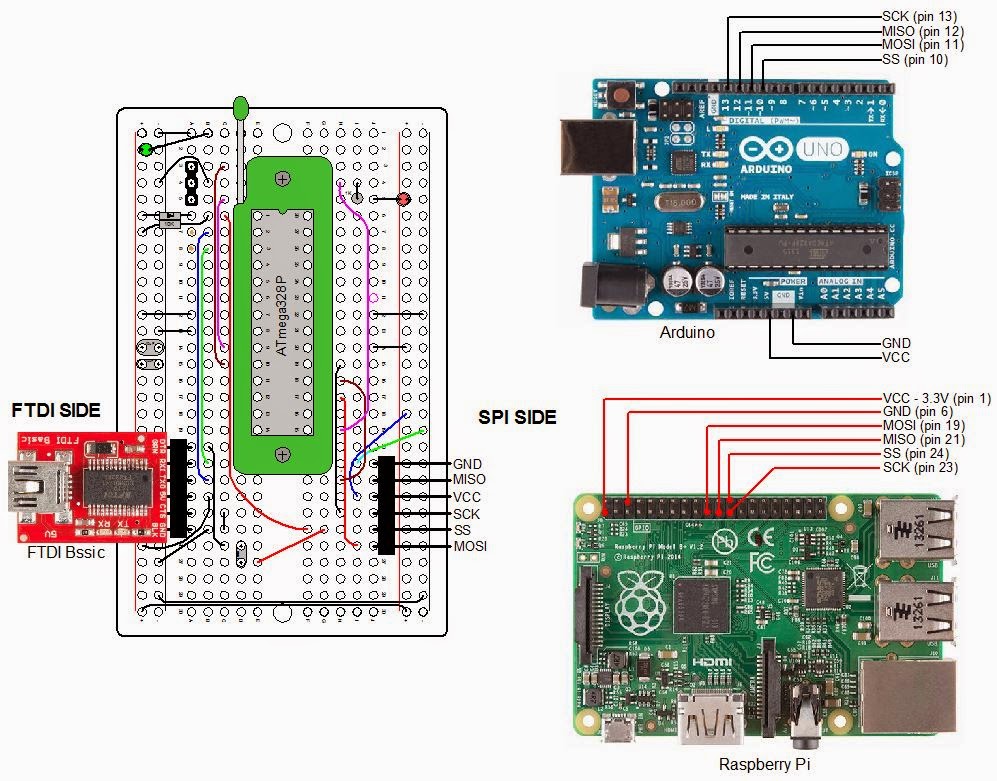
Here is the layout of the board with components and wiring:
Board Layout For The ATmega328P Programmer
Looking at the board layout, the ATmega328P sits in a 28 pin ZIF socket (all that green in the diagram). This allows an IC to be quickly inserted and removed. Check out the product page from Sparkfun.
The connector pins labeled SPI are for female - female jumper wires. This interface connects to the Raspberry Pi or to the Arduino Uno. Connections to the Raspberry Pi are to set the fusebits on an ATmega328P, and to load sketches developed on the Gertboard. The connections to the Arduino UNO are only to install a bootloader on an ATmega328P.
Note the interface labeled "FTDI". This interface is used to upload sketches to an ATmega328P (must have the bootloader installed) that I have developed on my Arduino. In addition, it provides access to the Arduino IDE Serial Monitor, allowing us to communicate with a program running on the jig's ATmega328P. FTDI is the name of a chip manufacturer that makes USB to Serial ICs. The FTDI interface on my jig connects to a Sparkfun FTDI Basic breakout board. This small board has a mini USB on one end and a six pin female connector on the other that plugs directly onto my jig.
There is a three pin female connector labeled resonator. Since the Gertboard and the Arduino Uno operate on different frequencies, the connector allows a 12MHz resonator to be connected for the Gertboard sketches and a 16MHz resonator for the Arduino operations.
There are two LEDs on the jig. The green one lights whenever power is applied to the jig. 5V can come from the FTDI board or the Arduino Uno. The Gertboard will supply 3.3V. The red LED is a sanity check and is connected to PB1 of the jig (this corresponds to pin 9 of the Arduino). After loading a bootloader, I can check if I can upload a sketch to a new ATmega528P by running a version of Blink. Anytime I need to check the jig or my connections, I can program that red LED.

Parts List

  • Prototype Breadboard PCB, half size: Adafruit 1609, $4.50
  • ZIP Socket, 28 pin: Sparkfun PRT-09175, $2.95
  • Right Angle Header Strip for FTDI and SPI: Mouser 571-9-103323-0, $2.24 for a strip of 40 pins
  • ATmega328P Microcontroller: Mouser 556-ATmega329K-PU, $3.55
  • Socket strip for Resonators: Digikey 1212-1125-ND, $3.89 for a strip of 64. Perfect socket for resonator pins
  • 16 MHz Resonator: Mouser 520-ZTT1600MX, $0.50
  • 12 MHz Resonator: Mouser 520-ZTT1200MX, $0.50
  • Red LED - clear housing: Digikey C503B-RCN-CW0Z0AA1-ND, $0.15
  • Red Green - clear housing: Digikey C503B-GCS-CY0C0791-ND, $0.24
  • 10μF, 16V Tantalum capacitor: Mouser 581-TAP106K016CRW, $0.53
  • 0.1μF 100V Ceramic capacitor: Mouser 1C20X7R104K100B, $0.18 ea.
  • 1N4148 diode: Mouser 512-1N4148, $0.10
  • 10KΩ Metal Film Resistor: Mouser 71-RN55D-F-10K, $0.10
  • 1KΩ Metal Film Resistor: Mouser 71-RN55D1001F/R, $0.10 ea.
I use LEDs with clear bodies. I anticipate using LEDs in battery powered projects so I want to minimize the current consumed by LEDs. Normally, you calculate the series resistor to deliver about 10ma. of current to drive the LED on. A resistor of about 330Ω is commonly used. The LEDs with the clear housings require much less current so I typically use a 1KΩ series resistor (about 2ma.). Even that can seem too bright, I might try 2KΩ on my next project.

Using the Jig

Diagram used for all situations follows:
Connecting The Programming Jig

Installing a Bootloader

Make connections as in the diagram above from the jig's SPI connector to the Arduino. Make sure there is a 16MHz resonator installed on the jig. Install an ATmega328P on the fixture. By the way, I probably should have mentioned it before, but do NOT use a ATmega328 unless you are capable of adding support for the device in avrdude and the Arduino IDE. The two devices have different signatures so the ATmega328 will not be recognized unless you are capable and willing to make the software changes I mentioned. The two devices are about the same but the "P" version runs at lower power.
Do the following from the Arduino IDE:
  1. Upload the sketch ArduinoISP: Files\Examples\ArduinoISP.
  2. Select the Arduino Uno board (selects the bootloader for the ATmega328P because that is the microprocessor for the Uno): Tools\Board\Arduino Uno.
  3. Select the Arduino as ISP as the programmer: Tools\Programmer\Arduino as ISP.
  4. Install the bootloader: Tools\Burn Bootloader.
That's all there is to it. It takes less than a minute for the process to complete. Once the TX and RX LEDs, on the Arduino, stop blinking, the bootloader is loaded.

Uploading Sketch Via FTDI

Once the boatloader is installed, you can upload a sketch to the jig using the FTDI Basic board. When I plugged my FTDI Basic into my USB port, for the first time, I found that the drivers had already been installed on my Windows 8.1 system. They must have been part of the Arduino IDE installation. If you do not have the drivers, check out Sparkfun's product page for instructions on getting them. The FTDI Basic costs about $15 at Sparkfun.

Raspberry Pi/Gertboard

The Gertboard is a expansion board that connects to the Raspberry Pi's GPIO pins. It has several different circuits useful for interfacing the Raspberry Pi to the outside world. The Gertboard works with all thee versions of the Raspberry Pi (A, B, B+). Here is what the Gertboard offers:
  • ULN2808 containing six open collector outputs, each capable of driving a 500ma. load up to 50V (from a separate power source)
  • MCP4802 dual channel D>A (digital to analog) converter
  • MCP3002 dual channel A>D (analog to digital) converter
  • ROHM BD6222HFP H bridge motor controller (need a separate power source)
  • 12 output buffer circuits
  • 12 input buffer circuits
  • 12 red LEDs
  • 3 momentary switches
  • ATmega328P microcontroller. Running on 3.3V with a 12MHz resonator. All IO pins are available.
The documentation, unbelievably not provided when you purchase the product, is excellent. It can be found here. The manual references C and python programs that can be used to test out each section of the Gertboard. In order to use the ATmega328P, a bit of software must be loaded in the Raspberry Pi. This is also referenced in the manual and is available from Gordon Henderson. Here is a link to his blog. It all just works great. Newark Element14 has the Gertboard for $40. Inexplicably, Sparkfun sells it for $60. On Sparkfun's product page it lists the microcontroller as an ATmega328. It's an ATmega328P.
My jig will look to the Raspberry Pi just like the ARmega328P on the Gertboard. Therefore, if you want to interface an ATmega328P to a Raspberry Pi without using the Gertboard, the same software from Gordon will do the job. Just make the connections as in the diagram above.
Once you upload a sketch, you may need to communicate with the ATmega328P, such as you do with an Arduino. For the Arduino, you use the Serial Monitor function of the Arduyino IDE. You will not be able to do that from the Raspberry Pi, but you can still communicate with the ATmega328P. You connect RX and TX on the FTDI side of the jig to TX and RX, respectively, on the Raspberry Pi. You connect the FTDI TX to pin 10 (RX) of the Pi and FTDI RX to pin 8 (TX) of the Pi. The alternative to the Serial Monitor is to use a terminal program like minicom within a terminal window on the Raspberry Pi. The installation and use of the minicom program is covered in the Gertboard User's Manual.

Going On From Here

Obviously, the jig as it stands, does not have much utility as it only uses one of the many ATmega328P's IO pins. However, the concept can be used to make something more useful. Here is an example of a project in the works:
All of this goes into an enclosure. I will add temperature sensors and a RF transmitter, with antenna. The ATmega328P is mounted in a standard 28 pin socket instead of the Zif socket. A 16MHz crystal provides the clock reference.
Note the FTDI basic board. It's used to communicate with the ATmega328P. This is necessary to tell the LCD what text to display. Once power is applied, the display is blank. I attach the FTDI Basic board, connect it to the PC, via a USB cable, and bring up the Arduino IDE. The sketch is already running on the ATmega328P so I click on the Serial Monitor and am greeted with a request to type a message. Once that is done, the message is displayed in a Time Square Scroll. I can then remove the FTDI Basic board.
Please check out my blog entries of March 7, 2013 to April 18, 2013 for discussions of my LCD projects for the Raspberry Pi. The last two posts, specifically, are about my Times Square Scroll software. I have since converted the software from python to C to run on the Arduino. I'll report on that effort at a later time.

Monday, October 20, 2014

DS18B20 12 Bit Resolution - What does that mean

DS18B20 Resolution

The following is from figure 2 of the Maxim Integrated data sheet: "DS18B20 Programmable Resolution 1-Wire Digital Thermometer"
When the data sheet talks about 12 bit resolution, what do they mean? From the figure above, you can see that two 8 bit bytes are reserved for the temperature measurement. That means there are a total of 16 bits. But, notice there are only 12 unique bits. Bits 11 to 15, of the most significant byte (MS Byte), will always be the same. If one bit is a "1", all 5 bits will be a "1". If one bit is a "0", all 5 bits will be a "0". That is where the 12 comes from: 12 unique bits.
How is that number related to resolution? Of those 12 bits, eight are reserved for the integer part of the number: bit 4 to bit 11. Bit 0, bit 1, bit 2, and bit 3 make up the fractional component. You can choose to have the DS18B20 measure with 9, 10, 11, or 12 bit resolution. If you choose 12 bits, all 12 bits are used in the calculation of temperature. If you choose 11 bits, the least significant bit will always be a 0. If you choose 10 bits, the last two bits will always be zero. If you choose nine bits, the last three bits will always be zero giving you only one fractional bit of resolution.
With nine bits, the least significant bit is bit 3. The value of bit 3 (from the figure above) is 2-1. That is the equivalent to 1⁄2 or 0.5. So, nine bits gives you a resolution of 0.5°C.. If you choose 12 bit resolution, the least significant bit has a value of 2-4. That gives you a resolution of 1⁄16 or 0.0625. So, 12 bits gives you a resolution of 0.0625°C..
Why would you want to choose anything other than 12 bit resolution? Why not always choose the best? The answer is speed. When asked for a temperature conversion, the DS18B20 takes multiple measurements and averages them before reporting the result. The higher the resolution, the larger the number of measurements go into the average, and the longer time to complete the conversion. The maximum conversion time for 12 bit resolution is eight times the maximum time for nine bit resolution. Here is a chart of resolution in bits, degrees, and maximum conversion time:
Number of Bits Resolution Maximum Conversion Time, ms.
9 0.5000°C 93.75
10 0.2500°C 187.5
11 0.1250°C 375
12 0.0625°C 750

Deriving Temperature From the Register Data - Temperatures below 0°C

The following is Figure 1 from the Maxim data sheet:
I hope it is clear how the decimal value of temperature relates to the binary digital output column when the temperatures are in the positive range. It might not be as clear when the temperatures are negative. Those binary numbers are really signed binary numbers. This means that the most significant bit, bit 11, or in this case, bits 11 through bit 15 (since these five bits are always the same), tell you if the number is positive or negative. If those bits are all "0"'s the number is positive. If those bits are all "1"'s the number is negative. However, that is only half the story. You might think that if +25.0625 is 0000 0001 1001 0001 then -25.0625 could be 1111 1001 1001 0001. But you see from the figure above that is not the case.
As small as the DS18B20 is, it has to have some computing power. Therefore, it shares characteristics with your microprocessor or microcontroller device. These devices all have some electronic circuitry that perform basic functions. One such function is to add binary numbers. Another is to change all the "1"'s to "0"'s and all the "0"'s to "1"'s. That operation is called inverting. A function that is not commonly implemented is circuitry to perform subtraction. That is because it is possible to subtract by using the two circuits I described, adding and inverting.
How would you subtract 13 from 25 without actually performing subtraction. Let's assume we were working with 8 bit signed binary numbers. 25 is 0001 1001. 13 is 0000 1101. Subtracting 13 from 25 is the same as adding -13 to +25. In order to facilitate the subtraction process, devices like the DS18B20 (because they must do some computing) represent negative numbers by what is called the two's complement of the number. The two's complement is formed by using the aforementioned processes, adding and inverting. First we invert then we add 1.
Let's get the two's complement of -13. First, we invert the 0000 1101 to get 1111 0010. Next, we add 1 yielding 1111 0011. When we add that to 0001 1001 (25) we get 1 0000 1100. Since we are using 8 bit signed binary numbers, that lonely "1" on the left gets lost giving us our final result of 0000 1100 which is decimal 12. This is how the DS18B20 represents the binary (and hex) temperatures that are below 0°C: by their two's complement. Let's prove it. If +25.0625 is 0000 0001 1001 0001. What is -25,0625 in two's complement? Let's invert 0000 0001 1001 0001 to 1111 1110 0110 1110 and add 1. This gives us 1111 1110 0110 1111, which is what is shown in the figure above.
If you want more information on two's complement, including some theory, I recommend this site.

Calculating Temperature From DS18B20 Register Values

When you get the results from the DS18B20, two bytes from the scratchpad, how do you convert them to temperature? Without getting theoretical, this is what I do:
  1. Multiply the value of the most significant byte (scratchpad byte 1) of the temperature data by 256.
  2. Add to the result of step 1, the the value of the least significant byte (scratchpad byte 0).
  3. Check to see if the temperature is negative by testing if the result from step 2 is over 127. If so the temperature is negative.
  4. If the temperature is negative, subtract the result of step 2 from 65536.
  5. Divide by 16